2nd Order System Block Diagram Damping Ratio Solved Figure 2
Order system second control block diagram frequency undamped natural feedback rad omega here Second-order system example #1 Solved problem 4: the step response of second-order system
Second order system
Solved figure 2. block diagram of standard second order Response step system order second damping poles overdamped ratio damped critically underdamped negative oscillation real g007 pone undamped open without Critically damped graph
Time response of second order system
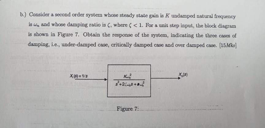
Solved b.) consider a second order system whose steady stateA second order control system is one wherein the Answered: second-order control system models one…Solved a block diagram of a second-order system is shown in.
Solved general 2nd order system and system modeling 1. forSolved (c) the dynamics of a second order control system is 7.1 second order underdamped systems – introduction to control systemsOrder second overshoot damping ratio system angle ece measured.

Order second response system underdamped 2nd graphical parameters fit graph time step rise peak ratio input decay period output calculate
Order second system block diagram state control solved representation question feedback transcribed problem text been show has gain loop spaceSolved figure 2. block diagram of standard second order Transfer function order system second damping ratio natural frequency help terms represented behavior generally dynamic following thenAnswered: consider the 2nd order system with….
Second-order system example #4Damping ratio Solved for a 2nd order system with a damping ratio of 0.707,Second order system.

Graphical method: second order underdamped
Everything modelling and simulation: modelling a basic second orderSecond order systems Solved: an under-damped 2nd order system with damping ratioOrder system damped critically damping second over circuits graph 2nd oscillate why time capacitor complex coefficient.
Solved question 5 the block diagram of a second-order systemStep response of a second-order system with respect to Numerical 1: determine the type of damping(2nd order control systemProblem 1: second-order system the block diagram of a.

Damping undamped damped resonant gain
Simulink modelling simulationUnderdamped second order system How to find damping ratio for block diagram || control system transfer10.2: frequency response of damped second order systems.
Second order systems 2.3Block diagram second order system shown solved Solved a second order system behaves as follow s: y + 2.5Solved q13. a second-order system is described by the.

Solved 2. question a typical 2nd order dynamic system,
Second order control system .
.

Time Response of Second Order System - Electronics Coach

Solved (c) The dynamics of a second order control system is | Chegg.com

Solved 2. Question A typical 2nd order dynamic system, | Chegg.com

Solved Q13. A second-order system is described by the | Chegg.com

Solved Figure 2. Block Diagram of standard second order | Chegg.com

10.2: Frequency Response of Damped Second Order Systems - Engineering

Second order system